Article
Benefit of Using Flow Limiting Valves with Modulating Temperature Control Valves

~Authored by Jerry Boulanger
Many statements have been made about the unsuitability of automatic flow control valves (more accurately called flow limiters) for use in tandem with modulating temperature control valves (TCV). This article will address the issue and show that these claims are not true.
In order to do a comprehensive analysis we will look at the following:
- What automatic flow limiting valves do
- The output vs. flow of the load(s) when control is provided by modulating the flow.
- A comparison between manual balance and automatic flow limiting
What Flow Limiters Do
Their function is to limit the flow to a pre-set value, and until the flow reaches that value the limiter is wide open and not concerned about the flow, similar to a current limiter or resistor in an electrical circuit. If some other device wants to control the flow at a lower value the limiter is “off duty”, wide open. In other words, in the flow range from shutoff to 100% design flow, the limiter is no different than any other fixed head loss component in the system.
What is happening within the branch over that span? In any conventional HVAC load that is controlled by modulating the flow rate through the heat exchanger (coil) with a 2-way valve, it is the control system that is responsible for varying the flow rate to match the load in the design range. The TCV is the muscle; it responds to commands from the controller/thermostat and moves to increase or decrease the flow as required. If it’s a welldesigned system in good operating condition it’s logical to assume that most of the time the flow rate required should be less than design. In fact, in a true constant-temperature variable flow load system, variable flow load it will have a non-linear output curve and should most often operate happily with a fraction of the design flow rate. At any flow lower than 100% the limiter will not be in play.
The Output vs. Flow Curve
This curve is important to the discussion because the ultimate objective of any system is to control the rate of heat transfer. Any load supplied with a constant water temperature and controlled by varying the flow will have a curve similar to Figure 1. The slope of the lower part of the curve is steep and 80% flow provides close to full output. We can conclude from this that the TCV (as part of the control system) needs to be capable of good control from shut-off to about 80% flow.
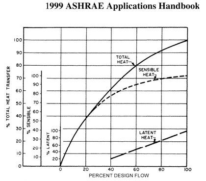
Figure 1
Note also that varying the flow from 80% to 100% and back only provides a small increase or decrease in the heat transfer.
Any analysis of TCV performance for non-linear loads should, therefore, look at not just TCV position but also the rate of heat transfer and relative flow rate.
The Comparison
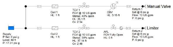
We will now move on to a computer model analysis of identical temperature control valves in branches which are also identical except for the balance device. The computer model has two branches – one with a flow limiter and one with a manual balance valve, it is running at 40% flow. The picture to the left is a run at 40% flow (about 60% output). Note the low coil head loss and high TCV pressure drop.
Common details are:
- Design flow rate of 25 gpm, branch differential head same for both @ 40’
- Coil loss 6’ @ 25 gpm, piping/fitting losses 4.2’ @ 25 gpm
- Equal percentage control valve, Cv 12.0, head loss 10.8’ @ 25 gpm, authority 27%
The manual valve is perfectly set to give design flow with a wide open control valve. The 2-32 psid range limiter design head loss is inserted as a Cv equivalent to 25 gpm @ 3 psid. (Griswold recommends a design head loss equal to 1.5 times the low end of the control range.)
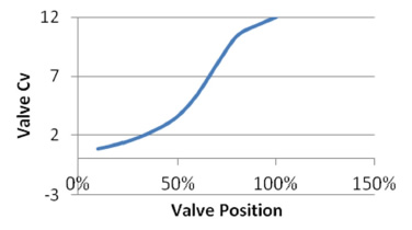
Note that the TCV authority is 27%, only slightly higher than the minimum of 25% recommended for modulating control valves in HVAC systems. The characteristic curve for the valve in the model is shown below. Not quite a classic equal % curve but likely representative of a typical TCV.
From the results chart we can see that below 60% flow and about 80% output the TCV valve positions are close to the same for all of the branches.
| FLOW | FLOW % | OUTPUT | CBV TCV POS. | LIMITER TCV POS. |
|---|---|---|---|---|
| 5 gpm | 20% | 35% | 20% | 20% |
| 10 gpm | 40% | 62% | 40% | 39% |
| 15 gpm | 60% | 80% | 53% | 52% |
| 17.5 gpm | 70% | 87% | 59% | 56% |
| 20 gpm | 80% | 92% | 65% | 61% |
| 22.5 gpm | 90% | 96% | 73% | 65% |
| 25 gpm | 100% | 100% | 100% | 70% |
This makes sense – at reduced flow the losses through fixed components in each branch (including the limiter) are quite low and the TCV must absorb most of the branch differential head to control the flow. So, for the critical control area on the coil curve the performance of the TCV is pretty much unaffected by the type of balance device.
Differences start to appear when the last few BTU are required to get to 100% heat transfer. The TCV in the manual branch must go to 100% while the TCV in the limiter branch gets there at 70%. The branch with the limiter will see no increase in flow as the valve moves from 70 to 100% open. It follows then that in order to regain authority over the flow, the TCV paired with the limiter will have to close to about 70% open. In other words, the top 30% of the valve stroke is has no impact on the flow. What will be the impact on heat transfer and controllability?
The answer is that it will be negligible. If the control system for a HVAC load has driven the TCV 100% open either a design load exists or the system can’t meet setpoint for some other reason. When conditions change such that the load is reduced, the control system will have to reduce flow/output. Based on the non-linear coil curve, it will have to effect a significant reduction in flow to see a minor reduction in output. To reduce the output by 8% requires a flow reduction of 20% and each of the TCV’s in the comparison must move to about the same position to do that. It’s likely, therefore, that gaining authority over the heat transfer rate will happen at about the same pace in both branches.
Other Factors
As always, there are a number of factors that will affect the performance of a real-world application. Among these are over-sizing of the coil, over-sizing of the control valve and/or balance valve, poor commissioning, maintenance and/ or operation, etc. All of the above can adversely affect the ability of the temperature control system to control the flow and by extension the rate of heat transfer. And, if the
application uses supply water temperature reset as part of the control strategy it’s a different ball game.

Do you have a question on this Application Tip or any of the Griswold Controls products? Fill out the form below and someone from Griswold Controls will get back to you shortly.
Questions about this application? Contact info@GriswoldControls.com, call 949.559.6000 or fill out the contact form on this page.