Article
3-Way Control Valves or Pressure Independent Valves?
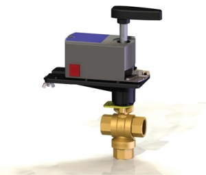
A 3-way control valve shuts off water flow in one pipe while opening water flow in another pipe. In a modulating or 3-point floating application the valve can also mix water from two different pipes into one pipe or divert water from one pipe into two different pipes. Connected to the Building Automation System and thermostats located in each zone, the 3-way valve directs the heating or cooling water through the coil if heating or cooling is required. If the zone does not need heating or cooling the flow is directed through the bypass line to the return piping. This means the flowrate will stay the same if you use 3-way valves in a system. In comparison a 2-way valve can stop water flow to the coil when there is no need for heating or cooling. This means the flowrate will vary if you use 2-way valves in a system.
Historically 3-way valves were used in constant flow pumping systems to maintain the same flow at all times whether there was a need for heating/cooling or not. Most systems today use 2-way valves for variable speed systems because the flowrate can fluctuate as valves open and close. As the 2-way valve closes the pressure differential increases and the pump slows down (less flow) which saves energy.
Most experts agree that variable flow pumping systems are preferred because they have the potential to save building owners significant pump energy cost. Some have switched their constant speed system to variable speed but they don’t capture the energy saving because they leave their 3-way valves or install 2-way valves and have overflow and underflow issues. With 3-way valves the variable speed system never experiences any energy savings because the 3-way valves maintain constant flow regardless of load changes and the pump can never reduce speed. When simple 2-way valves are installed there can be overflow and underflow conditions during start up and when valves are oversized which also wastes pump energy. Both of these problems can be solved by installing Pressure Independent Control Valves (PIC-V). A PIC-V maintains correct flow through each circuit or coil at all times even if the system pressure changes. The circuit has the exact flow it needs at start up, at design load and at reduced load. The flow is only changed when the control system requires a change.
No other control valve can deliver exact flow regardless of pressure changes. And if you are retrofitting your 3-way valves select a lower flowrate for the coil to provide a higher ΔT across coil. This reduced flow means the pump can reduce the speed and save energy.
There are challenges when all of the 2-way valves are shut off in a variable speed system:
- The pump may overheat when it continues to run against closed valves even at minimum speed.
- The temperature of the conditioned water in the headers and remote risers will eventually become the ambient temperature. This means that when a space eventually requires heating/cooling, there will be a delay as the freshly heated or cooled water circulates through the system. This may cause user discomfort and generate complaints.
Therefore it is good practice when converting from a 3-way system to 2-way system to leave the most remote 3-way valve in place on each riser so that cooling/heating water can recirculate even if all the other valves are closed.
Another issue with using 3-way valves in any type of application is they contribute to low ΔT syndrome. 3-way valves bypass conditioned heated/cooled supply water into the return line. The temperatures mix and the ΔT across the chiller or boiler is reduced because the supply water is mixed into the return.
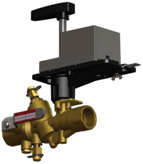
How does a Pressure Independent Control Valve work in your system? A PIC-V combines a differential pressure regulating diaphragm with a 2-way actuated control valve to supply a specific flow regardless of system pressure fluctuations. The valve performs the function of a balancing valve and control valve in one unit. The actuator modulates the PIC-V to a required fixed flow based on load or zone requirements, independent of pressure.
When the zone is satisfied the actuator stops rotating and the valve is now set at optimum flow. If the system pressure changes the internal pressure regulating diaphragm compensates for the pressure change and maintains constant flow rate without cycling by the actuator. The flow does not change until the control system tells the actuator to change the valve position based on load changes. This stable flow means less work for the actuator, and actuator life is therefore increased.

Do you have a question on this Application Tip or any of the Griswold Controls products? Fill out the form below and someone from Griswold Controls will get back to you shortly.
Questions about this application? Contact info@GriswoldControls.com, call 949.559.6000 or fill out the contact form on this page.